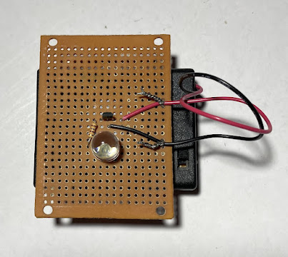
This article is about a simple Hall Effect sensor circuit made from AN503 IC (integrated circuit):
Figure 1: Hall Effect sensor Circuit.
This magnet (taken from an old speaker) was used to activate the Hall Effect sensor circuit:
Figure 2: Magnet taken from an old speaker.
You can see in the video that the bright LED turns OFF when the magnet approaches the Hall Effect sensor:
Step 1: Check the Datasheets for Pinout
You need to check the datasheets for the pinout of your Hall Effect sensor IC (integrated circuit):
Figure 3: Datasheet pinout.
The circuit is very simple. No design is required. According to the datasheet, the quiescent voltage is about 2.5 V. This voltage falls to zero when the magnet is placed near the sensor and the bright LED turns OFF. The LED voltage is 2 V. I connected an LED in series with a 100 ohm resistor to the IC (integrated circuit) output. The maximum LED current is equal to:
IledMax = (VoMax - Vled) / Rled
= (2.75 V - 2 V) / 100 ohms
= 7.5 mA
This current might be small. However, the LED seems to be very bright.
The supply voltage needs to be from 6 V to 4.5 V. Thus I used a quad AAA battery holder (4 AAA batteries connected in series).
Step 2: Make the Circuit
You can see the connection diagram here:
Figure 4: Make the Circuit.
The color code for the 100-ohm resistor is Brown, Black, and Brown which corresponds to:
Step 3: Testing
Testing showed that the circuit is working:
Figure 5: Testing.
Video:
Conclusion
The AN503 IC is actually a bit expensive. It costs about $5 USA.
You might ask yourself about the applications of this circuit. This circuit can detect magnetic fields.
When I was in high school about 20 years ago some kids were talking about using a reed switch (mechanical magnetic field sensor) for bikes. They were thinking of attaching a magnet to the wheel and a reed switch near the bike breaks to make a blinking LED.


No comments:
Post a Comment